Blogs


Welcome to PCI Blogs - selection of thoughts and tips shared by Project Controls community.

test

Brown Field Engineering

Brown Field Engineering

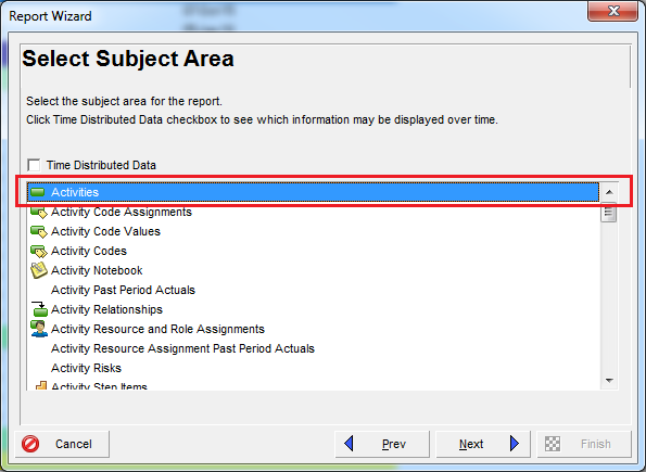
Modifications to an existing plant, for its expansion, debottlenecking etc., entail a set of specific engineering tasks and documents which are not found in a "Green Field" (new built) development.

As the modifications of the existing plant will lead to a change of operating conditions for its process equipment, their duty must be checked for the new conditions. This will entail, among others, the verification of the capacity of roating equipment, thermal duty of heat exchangers. Etc. Some of these verifications will need to be done by the equipment supplier itself, such as verification of compressors for new gas composition, distillation column trays for new gas/liquide traffic etc.

 Additionally, suitability of the equipment and piping for the new pressure and temperature conditions must be checked. Hydraulic calculations of pipework given the new flow conditions must be performed etc.


 Instruments, such as control valves and pressure saftey relief valves must also be checked so that they have adequate capacity to cover the new operating requirements.

In the case of new unit(s) being added to an existing facilities, it is more than likely that the new unit(s) will use some of the existing facility utilities. This could include fuel gas, electrical power, cooling medium, instrument air etc. Care must be taken while evaluating if the existing utilities have enough capacity: The current consumption need to be precisely assessed, taken into account the conditions of maximum consumption. Note that the spare capacity of the existing units might be less than that indicated in their original design documents due to modifications made to the plant since then!

 The additional load must also be estimated with sufficient accuracy as well. This will avoid a situation where the existing utilities fall short as the new design develops.

 On a physical stand point, addition to an existing plants will make use of the provision for "future" that was made in the original design. A new built facility indeed includes a certain level of pre-investment, such as 20% free space on pipe-racks, 20% free spare terminals in instrument junction boxes and multi-cables etc.

 Such space, if it has not been used up already, will be used for the extansion. Retrieval of the engineering drawings of the existing plant allowing identification of such free space is only the first step. As these drawings may not reflect the as-built condition of the plant and may not have been up-dated with later modifications, a physical check of the available free space is required. This requires to perform surveys.

 For above ground facilities, surveys range from simple visual or "measuring tape" type, to more extensive co-ordinates and elevations, up to the full 3D survey of an area.

 The 3D survey is performed by shooting numerous 2D pictures of an area of the plant from different view points. The pictures are then superimposed, yielding a 3D image. The later can be looked at and navigated in from the engineering office. The 3D picture is coordinated to the local plant coordinate system and scaled, which allows measurements.

 The point cloud 3D image of the existing plant can also be superimposed to new design in the 3D model, as shown on the picture here, to identify interferences.

 A 3D survey involves significant field and processing time besides expensive equipment. It is justified in the case of extensive modifications to a congested existing area. It will indeed allow to identify interferences, specially with small items such as small bore pipes, small E/I trays, supports etc. which do not appear on the existing drawings. In this case, it avoids numerous visits to the job site.

 It can also be useful to mitigate unavailability/unacurracy of existing drawings, provide measurements in unaccessbile areas, produce scaled drawings of the existing etc.

 Underground survey is done by means of excavations. The plot of land where a new unit is to be built, for instance, must be free of underground networks, such as pipes, cables etc. or their positions precisely known As available drawings may not depict all constructions having taken place over a number of years, an exploratory trench is commonly dug all around the area, up to the lowest level of expected networks, to identify any pipes, cable etc.

 Local excavation, of cable trenches, will allow to confirm that the free space that appear on existing drawings is still available for cables foreseen to be added in the trench.

 Although surveys might mitigate the unavailability of existing drawings, some existing documents are necessary. The addition of new lines on a pipe-rack for instance, will not only require the drawings of the existing steel work (which could be redrawn following survey if not available) but also its calculation note. The latter will indeed contain the information about its existing loading. Although the revamping engineer could estimate the pipe weights, loads sustained by the steel work to ensure pipe flexibility requirements, such as loads at fixed "anchor" points, cannot be guessed. They are found in the steel structure calculation note, as input data resulting from detailed piping stress calculations.

Once free spaces have been identified for the plant expansion, it needs to be booked. Physical markers are best, such as signs at tie-in locations, warning tape etc. Experience proves that co-ordination between a large plant various expansion projects is not often effective, especially between small projects under the Plant Engineering department and larger ones under dedicated project teams.

Knowledge of concurrent projects is essential for coordination to avoid conflict (both projects use the same plot space for instance).

The connections of the new facilities to the existing plant are called "tie-in’s". They consist of connections to the existing facilities pipe-work, electrical power distribution, instrumentation and telecom systems etc.

Doing some such connections will require the existing facility to be shut in, while others can be done while the plant is in operation. The Engineer will be able to minimize the former by discussing with the plant operator and find that, for instance, a piping tie-in can be relocated onto a line that can be temporarily put out of service etc. The existing design may also allow for tie-in’s during operation, such as that to a control system with redundant A/B circuits (operating with B while working on A then reversely), that to an electrical switchboard a section of which can be isolated etc. Detailed review and optimization ot tie-in’s will allow to reduce the number of tie-in’s requiring plant shutdown hence reduce downtime.

Tie-in schedules are issued by the concerned disciplines (Piping, Electrical, Instrumentation, Telecom).

Process discipline defines the required connections to the existing process and utility lines and initiates the Piping tie-in’s list. Verification is made of the adequacy of the existing lines design pressure and temperature with that of the new connecting lines.

Piping tie-in’s will entail the usual "tee" addition, where a branch is added on an existing line by "cut and weld" requiring the line to be shut in.

Addition of a branch connection during the operation of a line is also feasible by performing a "hot tap". In such case, a slightly larger and purposely made "tee", split in two halves, is welded to the live line. The tee is then fitted with a flange and an isolation valve. The hot tapping machine drills through the open valve while containing the fluid coming through the opening. A special device allows retention of the coupon. Once the drill is completed, the drilling equipment is retracted, the valve closed and the hot tap machine dismounted.

Controlled heat input during the welding operation of the hot tap tee to the live line is required. The pipe effective wall thickness will be indeed be reduced during welding due to the fusion of its outer surface (typical penetration is 2-3mm). The remaining wall thickness must be sufficient to hold the fluid pressure, or the latter shall be decreased.

 System modifications will entail that of:

   • Old systems, which are hard wired or have a hard logic, such as that contain in a ROM chip etc. Changes to these systems require their shutdown, for rewiring, replacement of the old chip with a new one etc.

   • New systems, which have a soft (configured) logic and distributed architecture: additional controllers can be added on-line while modifications on operators’ consoles (addition of mimics etc.) can be done on each console at a time, without impact on the other consoles. Even the controls (control loops) can be modified on the LIVE system, as controllers are usually duplicated A/B so that modifications can be done on A with B controlling, and then on B with A controlling.

 In both cases, the modifications of the system must be performed by the existing system supplier, which can be a constraint in terms of cost as there is no alternative. The Engineer merely provided the functional requirements, which the supplier implements.

 One may also find old systems which are obsolete and cannot be extended. I/O cards may for instance no longer been manufactured. Such systems must then be upgraded, i.e., replaced by new version.

Tie-in dossier will be submitted to the plant owner for review. They will include ad-hoc drawings, such as dismantling drawings showing what part of the existing plant has to be removed, e.g., a piece of pipe for incorporation of the branch "tee" connection etc.

Up-dating of plant documentation by its owner is rarely done properly. A project often develops new drawings instead of up-dating the existing drawings. The owner ends up with two drawings instead of one, one showing the existing plant and another one showing what has been added by a given project. Consolidation has to be done later on to a single drawing.

One issue faced is that several projects might be making concurrent modifications to the same part of the plant hence the same drawing. Having each of them up-date the same existing drawing in parallel is not acceptable and a drawing check out/check in system must be put in place: Project B, which "checked out" a certain drawing, must return, i.e. "check in", such drawing before it is provided ("checked out") to Project A.

Continue reading
5801 Hits
0 comments

How to install Primavera P6 Professional 16.1 Stand-alone


1

Click on Setup

Select “Typical” and click OK


3

Click Install

4

After installation complete, click OK.

5

In Driver type drop-down list, select “P6 Pro Stand-alone (SQLite)”, then click Next

6

Select “Add a new standalone database and connection”. Click Next

7

Enter new password. For example “admin”. Click Next

8

You can change destination of database file, otherwise it will be stored in My Document folder.

Check on “Load Sample Data” if you want some sample project appear in your database. Uncheck it if you want your database is blank. To create database for working, we usually uncheck it.

Click Next

9

Click Finish

10

You have finished the installation.

Now we open the application.

In Start menu click on P6 Professional R16.1

Enter password. For example “admin”. Click OK

11

Click OK again. We will turn that notification off when we’re inside program.

12

Go to Admin -> Admin Preferences

Go to Industry tab and select your industry. For example “Engineering and Construction”. Then click on Close.

14

Congratulation. Now you can plan with Primavera P6.

Happy Planning:-)

Tags:
Continue reading
6526 Hits
0 comments

Create activity list report include predecessors and successors


Sometimes you need to make an activity table report which also show predecessors and successors of each activity.

Here are the step how to do it.

Go to Report window and click “+” button to create a new report.

1

At “Select Subject Area” dialog, Select Activities.

2

At “Select Additional Subject Areas” dialog, Select Predecessors and Successors

3

Select Predecessors, Click Column

4

Select column you want to show. For example : Activity ID and Name. Then you should click Edit column to change the title.

56

7

You will do the same with the Successors.

Now you can print the report like this:

It show Predecessors and Successors for each activity.


Tags:
Continue reading
13368 Hits
0 comments

Scheduling and the ‘Progress Override v Retained Logic’ Conundrum

Scheduling and the ‘Progress Override v Retained Logic’ Conundrum

With the growing use of project management software to analyse construction delays, comes the often overlooked question – how does the software really work? This is of course a pretty meaty query and way too big for a single article. But within it are some more manageable ‘bite-sized’ issues. One of these is programme scheduling and how out-of-sequence working is rationalized by the software during the scheduling process. Now whilst some might consider the usefulness of this topic limited to the planners’ amongst you, it is important to recognise its wider implications upon defining and quantifying critical path delays.


So what is ‘programme scheduling’?
 
In a nutshell, scheduling is the process of updating a programme to a certain date during the course of a project (often referred to as the ‘data date’) by incorporating progress information for all activities in the programme up to that point in time. On many projects this is done at least once a month, with the updated programme included in the monthly progress report. The process itself involves adding actual start/finish dates, the percentage complete, and remaining duration of individual activities that have in some way changed over the reporting period. Once this information is added, the programme is scheduled (or rescheduled), calculating new start/finish dates for all activities in the programme according to a bunch of preset logic rules defined by the operator.
 
The average construction programme invariably contains many thousands of these user defined logic rules. These rules transform a static bar chart into a much more useful dynamic model which can be gradually updated with progress and other changes to assist managing the project and tracking delays. These rules include things like:- (a) logic relationships between activities (e.g. task A must be complete before task B can start); (b) different working-day calendars for specific types of tasks; and (c) resource dependent activity durations.
 
In addition, they also include a choice between using the Progress Override or Retained Logic options when dealing with out-of-sequence progress of activities (i.e. when an activity progresses in advance of when it otherwise would have according to the prevailing logic rules). When the Progress Override option is chosen, work is allowed to proceed on the out-of-sequence activity immediately and the logic links from its predecessor activities are overridden. If the Retained Logic option is chosen, these predecessor links are not overridden and remain in force thereby governing when the remainder of the out-of-sequence activity will be carried out.
 
Figure-1 and 2 are included below to help show the difference between these 2 operations.
Figure-1 shows 2 activities, A and B, where activity A was planned to be fully complete before the start of B. This is known as a finish-to-start logic link.
 
Figure-2 then demonstrates how the software deals with the situation where, during the works, activity B starts before A is complete. If the Retained Logic option is used, the remaining duration of activity B is scheduled to occur after A is complete. In contrast if the Progress Override option is chosen, then the finish-to-start logic between activity A and B is ignored or overridden. In this case activity B is allowed to progress notwithstanding that A is not finished.
 
 
The end result is that the Progress Override option leads to an earlier projected finish date for activity B. It also means that activity A is no longer on the critical path at the time of the progress update.
 
The wider implications of this choice will hopefully become clearer after working through an example. Consider a hypothetical reclamation project with a contract duration of 8 months. Upon commencement the Contractor is to carry out preliminary site investigation of the seabed and then prepare a detailed dredging layout plan. Once this is approved by the Engineer, the Contractor is to proceed with dredging, followed by construction of a rock filled seawall. The final stage is to place sand fill behind the seawall up to formation level. The corresponding programme is set out in Figure-3 below.
 
 
Now consider the situation as at the end of Month-2. Say that site investigation and drawing preparation proceeded as-planned. However, whilst generally accepting the submitted dredging layout, the Engineer would not formally approve the drawing until he had ‘checked a few things’. In response the Contractor decided to proceed with dredging and make any minor amendments (if necessary) after final approval was received. By doing this the Contractor was able to progress dredging at the planned rate so that up to the end of Month-2 it was around 30% complete, and there was no actual delay to dredging.
The status at the end of Month-2 can therefore be shown in 2 ways. The first is shown in Figure-4a (using Progress Override) and 2nd in Figure-4b (using Retained Logic).
 
 
The most sensible view of status at the end of Month-2 is clearly that shown in Figure-4a. As soon as dredging commenced it became critical, and the ongoing late ‘formal’ approval of the dredging layout dropped off the critical path. The alternative view, shown in Figure-4b, is that progress of dredging was being critically delayed by late approval of the layout drawing. Moreover this delay already amounted to around 10 days. In this situation therefore, the Progress Override option provides the most sensible outcome.
 
Let’s now take the example a bit further. Assume that the dredging layout is finally approved early in Month-3, but the remaining dredging work is immediately suspended by the Engineer pending a comprehensive design review. Moreover this suspension remains in place up to the end of Month-6. Shortly after dredging is suspended, and with knowledge that this might last for several months, the Contractor carried out some preliminary filling work at the seawall trench. This was done to protect the small section of dredged trench from damage and siltation, and amounted to only 2% of the total filling. The 2 possible outcomes after rescheduling the programme are shown in Figure-5a (using Progress Override) and Figure-5b (using Retained Logic).
Figure-5a and 5b give a very different result compared to Figure-4a and 4b. This time the Retained Logic option produces the most sensible outcome (see Figure-5b). The occurrence of out-of-sequence filling in these circumstances should not override the prevailing logic. Clearly the critical issue affecting progress from the start of Month-3 to the end of Month-6 was the suspension to dredging, and this governed the earliest projected date for completing the Works.
The table below compares the different outcomes produced by the Retained Logic and Progress Override options. It is submitted that the most sensible result is that the 2 events have caused critical delay amounting to 110 days. Moreover this outcome is achieved by using a combination of the 2 scheduling options. Using only the Progress Override option underestimates the impact, whilst the Retained Logic function overestimates it.
 
The example above is a reminder that slavishly using one or other of the 2 scheduling options discussed here can lead to errors in defining the critical path, as well as the extent of critical path delays. If not treated carefully, this simple programming function can have significant consequences with respect to entitlement to time and money.
Continue reading
9667 Hits
0 comments

Make report to Show only some WBS in Gantt chart


Sometime you need to make a report which focus on some WBS only. Like in this picture:

1

However, the Gantt chart show all other bar and make you distracted.

How about we can make it like this:

Well, much more cleaner. All unnecessary bars is hidden.

I will show you how.

Right click on Gantt chart area. Click on Bar:

You select the Bar which is showed in Gantt chart. By default the “Show bar when collapsed” option is checked. Now you uncheck them:

4

You will do this for each bar.

Then you will have a very clean Gantt chart.

Tags:
Continue reading
6310 Hits
0 comments

What does The Carat (^) Symbol next to the Resource Price/Unit in Primavera P6 mean?


1

The carat (^) is displayed when the resource does not have a price/unit assigned.


If resource does not have price/unit, Primavera will use the Project level price/unit which is defined in Project window -> Calculation tab

Now if you define price/unit for the resource like this:

Primavera will now use the price/unit from resource.

However you have to run “Tool -> Recalculate Assignment Costs” to refresh the data.

Click on Recalculate

5

Now you can see there is no carat (^) symbol in the price/unit and that price is taken from Resource.

Tags:
Continue reading
14233 Hits
0 comments

Categories

Search