Modifications to an existing plant, for its expansion, debottlenecking etc., entail a set of specific engineering tasks and documents which are not found in a "Green Field" (new built) development.
As the modifications of the existing plant will lead to a change of operating conditions for its process equipment, their duty must be checked for the new conditions. This will entail, among others, the verification of the capacity of roating equipment, thermal duty of heat exchangers. Etc. Some of these verifications will need to be done by the equipment supplier itself, such as verification of compressors for new gas composition, distillation column trays for new gas/liquide traffic etc.
Additionally, suitability of the equipment and piping for the new pressure and temperature conditions must be checked. Hydraulic calculations of pipework given the new flow conditions must be performed etc.
Instruments, such as control valves and pressure saftey relief valves must also be checked so that they have adequate capacity to cover the new operating requirements.
In the case of new unit(s) being added to an existing facilities, it is more than likely that the new unit(s) will use some of the existing facility utilities. This could include fuel gas, electrical power, cooling medium, instrument air etc. Care must be taken while evaluating if the existing utilities have enough capacity: The current consumption need to be precisely assessed, taken into account the conditions of maximum consumption. Note that the spare capacity of the existing units might be less than that indicated in their original design documents due to modifications made to the plant since then!
The additional load must also be estimated with sufficient accuracy as well. This will avoid a situation where the existing utilities fall short as the new design develops.
On a physical stand point, addition to an existing plants will make use of the provision for "future" that was made in the original design. A new built facility indeed includes a certain level of pre-investment, such as 20% free space on pipe-racks, 20% free spare terminals in instrument junction boxes and multi-cables etc.
Such space, if it has not been used up already, will be used for the extansion. Retrieval of the engineering drawings of the existing plant allowing identification of such free space is only the first step. As these drawings may not reflect the as-built condition of the plant and may not have been up-dated with later modifications, a physical check of the available free space is required. This requires to perform surveys.
For above ground facilities, surveys range from simple visual or "measuring tape" type, to more extensive co-ordinates and elevations, up to the full 3D survey of an area.
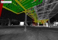
The 3D survey is performed by shooting numerous 2D pictures of an area of the plant from different view points. The pictures are then superimposed, yielding a 3D image. The later can be looked at and navigated in from the engineering office. The 3D picture is coordinated to the local plant coordinate system and scaled, which allows measurements.
The point cloud 3D image of the existing plant can also be superimposed to new design in the 3D model, as shown on the picture here, to identify interferences.
A 3D survey involves significant field and processing time besides expensive equipment. It is justified in the case of extensive modifications to a congested existing area. It will indeed allow to identify interferences, specially with small items such as small bore pipes, small E/I trays, supports etc. which do not appear on the existing drawings. In this case, it avoids numerous visits to the job site.
It can also be useful to mitigate unavailability/unacurracy of existing drawings, provide measurements in unaccessbile areas, produce scaled drawings of the existing etc.
Underground survey is done by means of excavations. The plot of land where a new unit is to be built, for instance, must be free of underground networks, such as pipes, cables etc. or their positions precisely known As available drawings may not depict all constructions having taken place over a number of years, an exploratory trench is commonly dug all around the area, up to the lowest level of expected networks, to identify any pipes, cable etc.
Local excavation, of cable trenches, will allow to confirm that the free space that appear on existing drawings is still available for cables foreseen to be added in the trench.
Although surveys might mitigate the unavailability of existing drawings, some existing documents are necessary. The addition of new lines on a pipe-rack for instance, will not only require the drawings of the existing steel work (which could be redrawn following survey if not available) but also its calculation note. The latter will indeed contain the information about its existing loading. Although the revamping engineer could estimate the pipe weights, loads sustained by the steel work to ensure pipe flexibility requirements, such as loads at fixed "anchor" points, cannot be guessed. They are found in the steel structure calculation note, as input data resulting from detailed piping stress calculations.
Once free spaces have been identified for the plant expansion, it needs to be booked. Physical markers are best, such as signs at tie-in locations, warning tape etc. Experience proves that co-ordination between a large plant various expansion projects is not often effective, especially between small projects under the Plant Engineering department and larger ones under dedicated project teams.
Knowledge of concurrent projects is essential for coordination to avoid conflict (both projects use the same plot space for instance).
The connections of the new facilities to the existing plant are called "tie-in’s". They consist of connections to the existing facilities pipe-work, electrical power distribution, instrumentation and telecom systems etc.
Doing some such connections will require the existing facility to be shut in, while others can be done while the plant is in operation. The Engineer will be able to minimize the former by discussing with the plant operator and find that, for instance, a piping tie-in can be relocated onto a line that can be temporarily put out of service etc. The existing design may also allow for tie-in’s during operation, such as that to a control system with redundant A/B circuits (operating with B while working on A then reversely), that to an electrical switchboard a section of which can be isolated etc. Detailed review and optimization ot tie-in’s will allow to reduce the number of tie-in’s requiring plant shutdown hence reduce downtime.
Tie-in schedules are issued by the concerned disciplines (Piping, Electrical, Instrumentation, Telecom).
Process discipline defines the required connections to the existing process and utility lines and initiates the Piping tie-in’s list. Verification is made of the adequacy of the existing lines design pressure and temperature with that of the new connecting lines.
Piping tie-in’s will entail the usual "tee" addition, where a branch is added on an existing line by "cut and weld" requiring the line to be shut in.
Addition of a branch connection during the operation of a line is also feasible by performing a "hot tap". In such case, a slightly larger and purposely made "tee", split in two halves, is welded to the live line. The tee is then fitted with a flange and an isolation valve. The hot tapping machine drills through the open valve while containing the fluid coming through the opening. A special device allows retention of the coupon. Once the drill is completed, the drilling equipment is retracted, the valve closed and the hot tap machine dismounted.
Controlled heat input during the welding operation of the hot tap tee to the live line is required. The pipe effective wall thickness will be indeed be reduced during welding due to the fusion of its outer surface (typical penetration is 2-3mm). The remaining wall thickness must be sufficient to hold the fluid pressure, or the latter shall be decreased.
System modifications will entail that of:
• Old systems, which are hard wired or have a hard logic, such as that contain in a ROM chip etc. Changes to these systems require their shutdown, for rewiring, replacement of the old chip with a new one etc.
• New systems, which have a soft (configured) logic and distributed architecture: additional controllers can be added on-line while modifications on operators’ consoles (addition of mimics etc.) can be done on each console at a time, without impact on the other consoles. Even the controls (control loops) can be modified on the LIVE system, as controllers are usually duplicated A/B so that modifications can be done on A with B controlling, and then on B with A controlling.
In both cases, the modifications of the system must be performed by the existing system supplier, which can be a constraint in terms of cost as there is no alternative. The Engineer merely provided the functional requirements, which the supplier implements.
One may also find old systems which are obsolete and cannot be extended. I/O cards may for instance no longer been manufactured. Such systems must then be upgraded, i.e., replaced by new version.
Tie-in dossier will be submitted to the plant owner for review. They will include ad-hoc drawings, such as dismantling drawings showing what part of the existing plant has to be removed, e.g., a piece of pipe for incorporation of the branch "tee" connection etc.
Up-dating of plant documentation by its owner is rarely done properly. A project often develops new drawings instead of up-dating the existing drawings. The owner ends up with two drawings instead of one, one showing the existing plant and another one showing what has been added by a given project. Consolidation has to be done later on to a single drawing.
One issue faced is that several projects might be making concurrent modifications to the same part of the plant hence the same drawing. Having each of them up-date the same existing drawing in parallel is not acceptable and a drawing check out/check in system must be put in place: Project B, which "checked out" a certain drawing, must return, i.e. "check in", such drawing before it is provided ("checked out") to Project A.

 Australia
 International


 Blogs
Blogs Glossary
 Templates
 Videos
 Paperback Literature